Optimisation of the aerodynamic properties of wind turbine rotor blades
Increasing the area efficiency of wind farms
Research consortium
Numerical and experimental investigations of knitted wire mesh structures for aerodynamic optimizations of wind turbine blades
Prof. Dr. Franz-Josef Peitzmann, Jan Hauke Harmening
In the research project Aeroblade funded by the ZIM program a novel type of knitted wire mesh structures is developed using CFD simulations to optimize the aerodynamics of wind turbine blades. The objective is to increase the power output of wind parks by 2 % to 5 %.
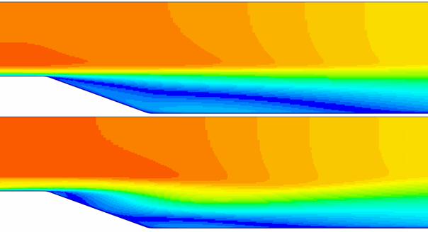
Simulations demonstrate that the knitted wire mesh generates streamwise vortices that significantly reduce the flow separation at a backward-facing step. The knitted wire mesh not only delays the flow separation but also reduces the separation bubble by 27.1 % (Figure 1 and 2).
The detailed results of this study were published in a scientific journal. The article is freely available at https://www.mdpi.com/2311-5521/7/12/370.
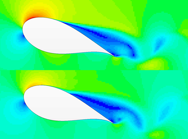
First investigations of the NREL 5MW turbine also show a beneficial effect. At an angle of attack of 18° the separated flow on the DU99W350 airfoil is delayed. This reduces the drag and increases the lift of the blade (Figure 3).
The aerodynamic effect of the knitted wire meshes was further investigated in a wind tunnel. For the experiments, different kinds of knitted wire mesh obtained from the project partner Eloona were placed on a cylinder and drag forces as well as velocities and turbulence quantities were measured. Figure 4 exhibits the experimental set up in the wind tunnel test section.
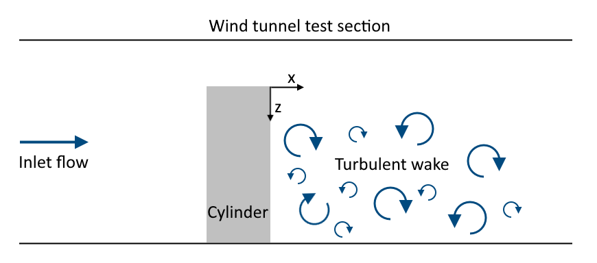
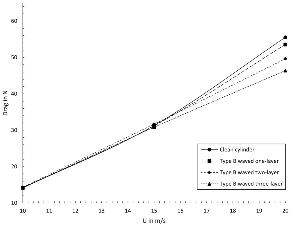
Figure 5 shows the results of the drag force measurements for one kind of knitted wire mesh that was deployed using multiple layers on the downwind side of the cylinder. As seen, significant reductions of the drag forces could be achieved especially in the case of elevated Reynolds numbers (up to 16.5%). This effect was the stronger the more layers were applied.
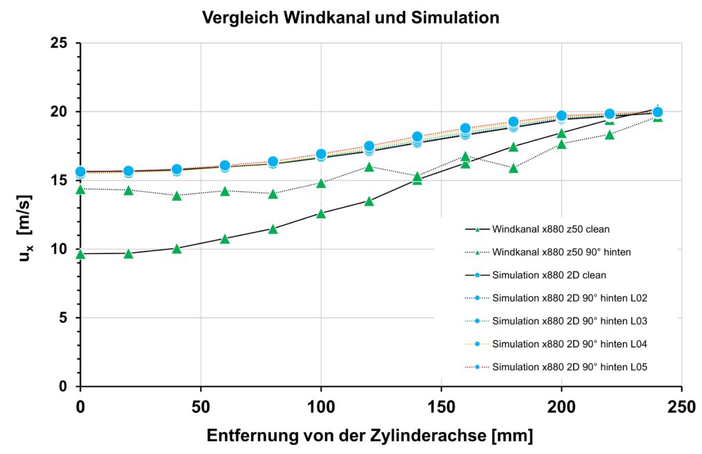
Beneficial effects could also be observed in the wake of the cylinder. Figures 6 and 7 exhibit the results for the axial velocities as well as the turbulent kinetic energy. The figures visualize the measured quantities in the wake of the cylinder at two different positions over the wind tunnel ground wall. As seen in Figure 6, the knitted wire mesh reduced the velocity deficit in the wake. This implies that the usable kinetic energy could be increased by applying the knitted wire mesh on the cylinder. As seen in Figure 7, furthermore, a significant reduction of the turbulent kinetic energy could be observed.
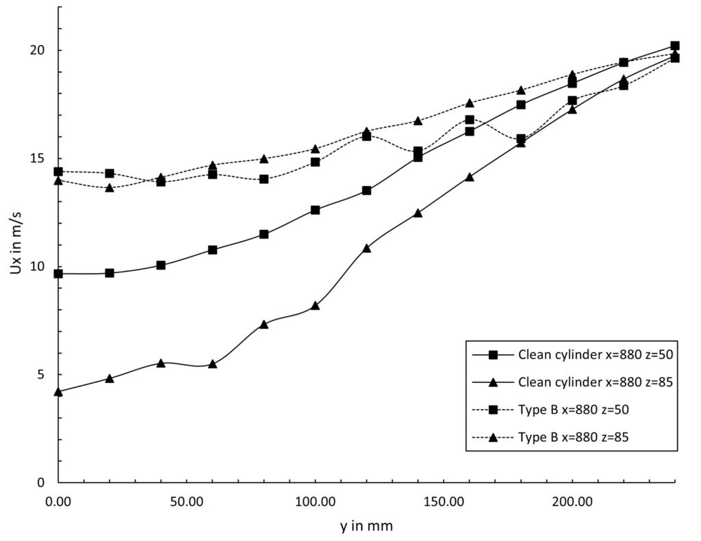
The results were obtained for one kind of knitted wire mesh positioned on the downwind side of the cylinder. Only one half of the symmetric wake is shown.
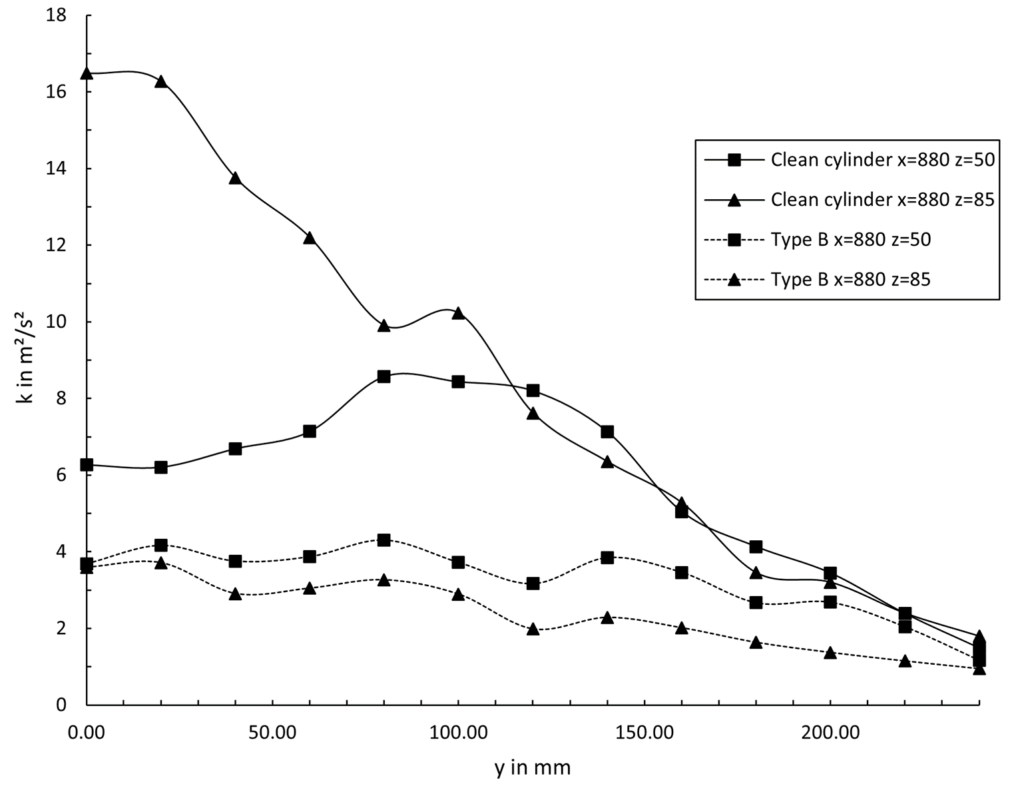
The results were obtained for one kind of knitted wire mesh positioned on the downwind side of the cylinder. Only one half of the symmetric wake is shown.
The results of this experimental investigation show that a flow can be favorably affected by deploying knitted wire meshes. For one thing, drag forces could be decreased significantly which increases the energy yield of a wind turbine. For another thing, the loss of kinetic energy in the wake as well as the level of turbulence could be reduced. This could increase the energy yield and lifetime of a second turbine installed downstream and could potentially lead to a reduction of the required distance between the two sequential turbines.
Contact: Franz-Josef Peitzmann // Westfälische Hochschule // Münsterstraße 265 // 46397 Bocholt // Tel.: 02871 2155 916
Development of CFD simulation models
Optimisation of the aerodynamic surface of rotor blades
Design of innovative surface structures from fine wire meshes
Prof. Dr.-Ing. Volker Kassera, Klaus-Peter Helbig, René Thümmler
CFD Consultants GmbH, based in Rottenburg am Neckar, is a long-standing service provider in the field of computational fluid dynamics (CFD). As part of the Aeroblade research project, the aim is to be able to analyse a customer’s wind turbines (WT) in the future and optimise them by means of a CFD simulation and evaluation of the existing situation in the wind farm. Based on the simulations carried out, surface structures made of knitted wire mesh are applied to the rotor blades and contribute to an increase in the performance of the wind farm.
One challenge of the research project is to find solution approaches that are able to describe local, small-scale turbulence effects sufficiently accurate and to map these effects in a large-scale effective volume. In any case, this challenge places the highest demands on the use of the necessary computer hardware and on data handling due to the enormous amounts of data to be expected. For this purpose, both our own computing clusters and the computing capacities of the High-Performance Computing Center Stuttgart (HLRS) with the supercomputer HAWK are used.
Due to the occurrence of these enormous differences in the size of the physical phenomena, the numerical flow simulation (CFD) is divided into micro- and macrosimulations.
The micro-simulation, carried out by our research partner Westfälische Hochschule Bocholt, simulates all flow processes near the rotor blade of the wind turbine in order to map the fluid-dynamic boundary layer with the transitions from laminar to turbulent and other turbulences. The aim is to manipulate the boundary layer of the rotor blade for as long as possible over the length and width of the profile in such a way, that the wake contains as little macroscopic turbulence as possible and the aerodynamic efficiency of the blade increases by delaying or reducing the stall.
The unification of the simulation results from the microsimulation with the macrosimulation requires a manipulation of the simulation tools (algorithm, boundary layer calculation, insertion of an empirical or calculated model), because due to the scale differences (small-scale wires in the mesh with about 1mm diameter/ large-scale WT wake with up to 2km length) no resolution of the wire mesh in the macro model is possible.
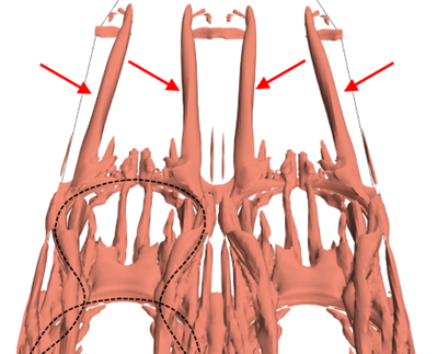
Solution of the scaling problem by developing a numerical replacement system that allows significantly larger calculation cells:
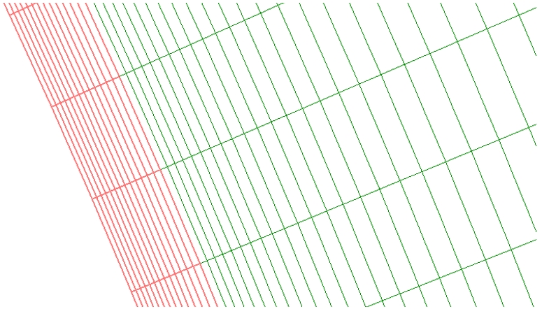
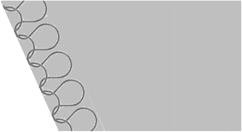
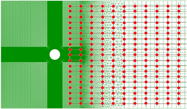
In a research geometry, the calculations were compared with numerically resolved and numerically modelled knitted fabrics. The results show good agreement:
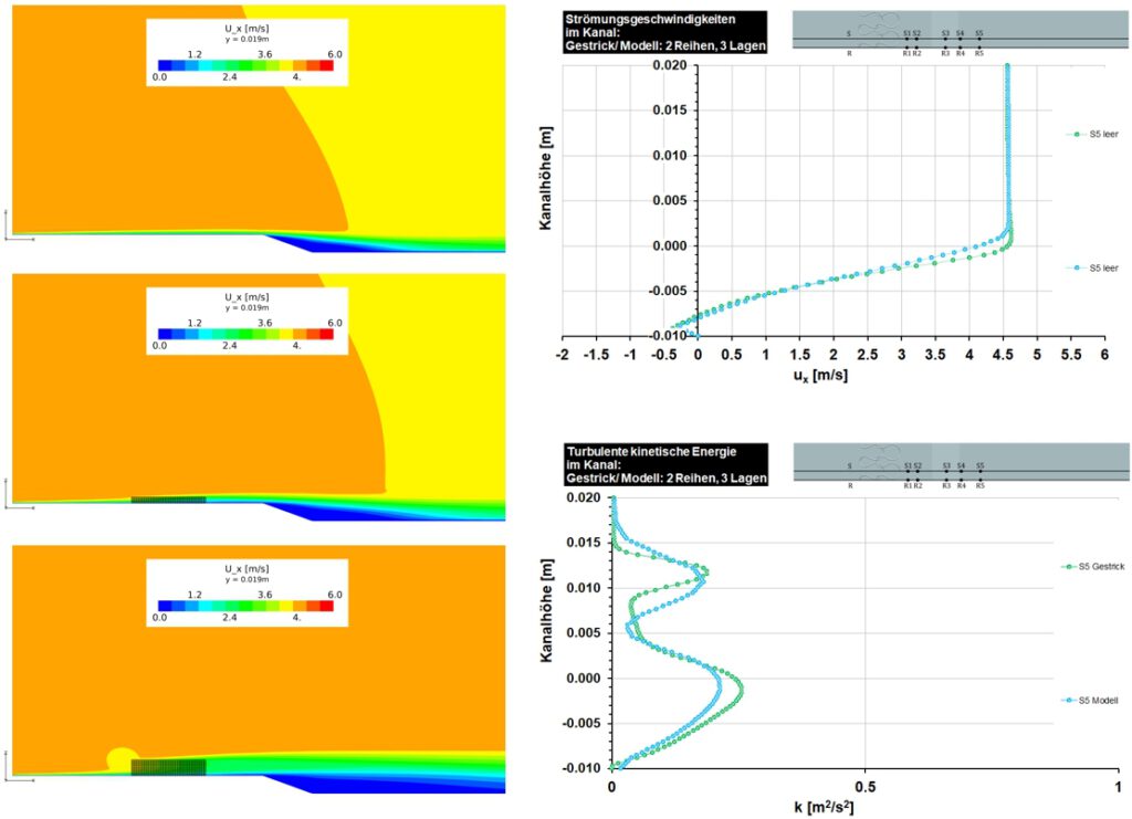
The wind tunnel tests of the flow around the cylinder with and without wire mesh were also investigated numerically. 2D simulations also show the influence of the knitted fabric on the wake.
Development of a measuring system: Within the project, the macroscopic calculation model for one type of wind turbine is developed as an example, since no high-resolution calculation models exist for the wake of wind turbines.
In order to assess how fine the meshing of the calculation model must be for the macrosimulation, a measurement system is being developed that analyses turbulence variables in the wake of a wind turbine.

With the help of this measuring system, changes in turbulence in the wake due to changes in the surface of the rotor blades through applications of wire mesh can be made visible.
Contact: Volker Kassera // CFD Consultants GmbH // Gartenstr. 82 // 72108 Rottenburg // Tel.: +49 7472 969460
Development of material systems for microperforated, turbulence-inhibiting coatings for rotor blades
Robert Ruf
eloona GmbH is a manufacturer of technical knitted wire meshes for demanding applications.
The Aeroblade research project aims to develop material systems based on knitted wire meshes in order to equip rotor blades with a turbulence-inhibiting coating or surface.
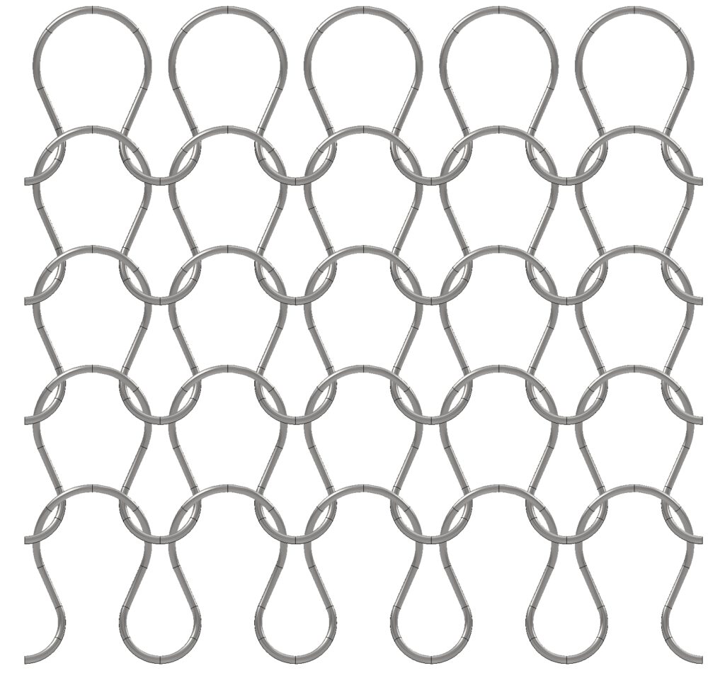
In the initial calculations, stainless steel wire meshes with defined, mutually coordinated mesh lengths and mesh spacings with an average wire diameter were used.
We are able to process almost all materials, especially stainless steels and special materials in the range of 0.05 – 0.80 mm depending on the system conditions. In addition, there are material combinations as well as multi-thread variants and designs.
Contact: Robert Ruf // eloona GmbH // Gewerbepark 12 // 91785 Pleinfeld // Tel.: +49 9144 96 99 100